Last Updated: Jul 20, 2020
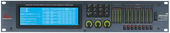
DriveRack® 480 Series
Firmware Updater
Introduction
The I LaJ494P is a popular electronic component, specifically an integrated circuit (IC) designed for various applications. A schematic diagram is a crucial tool for understanding the internal workings and connections of this IC. In this write-up, we'll explore the I LaJ494P schematic and what makes it "better" in terms of design, functionality, and applications.
Overview of I LaJ494P
The I LaJ494P is a type of voltage regulator IC, commonly used in power supply circuits, audio amplifiers, and other electronic systems. This IC is known for its high performance, reliability, and versatility. The "I" in I LaJ494P likely indicates that it's an integrated circuit, while "LaJ494P" might represent the specific part number or code assigned by the manufacturer.
Schematic Diagram
A schematic diagram is a visual representation of the internal circuitry of the I LaJ494P IC. It illustrates the connections between various components, such as transistors, resistors, capacitors, and diodes, which make up the IC. A well-designed schematic diagram is essential for:
What Makes a Schematic "Better"?
A "better" schematic diagram for the I LaJ494P IC would possess the following characteristics:
Benefits of a Well-Designed Schematic
A well-designed schematic diagram for the I LaJ494P IC offers several benefits:
Conclusion
In conclusion, a well-designed schematic diagram is essential for understanding and working with the I LaJ494P IC. By incorporating characteristics such as clarity, completeness, standardization, and detail, a "better" schematic diagram can be created. This, in turn, leads to improved performance, reduced design time, and easier troubleshooting. As electronics continue to advance, the importance of high-quality schematic diagrams will only continue to grow.
The search for an "i laj494p schematic" typically points toward the IL494P or TL494 integrated circuit, which is a staple in the world of Pulse Width Modulation (PWM) control. Whether you are repairing an old ATX power supply or designing a custom DC-to-DC converter, understanding why one schematic is "better" than another comes down to application-specific optimization.
Below is a detailed guide on evaluating and selecting the best schematic for this versatile controller. Understanding the Core: The IL494P / TL494 Architecture
Before determining which schematic is superior, it is essential to understand what the chip does. The IL494P (often a specific brand’s designation for the industry-standard 494 family) contains: Two error amplifiers. An adjustable oscillator. A dead-time control (DTC) comparator. A pulse-steering flip-flop. A 5V precision regulator. Output control transistors. What Makes a Schematic "Better"?
A "better" schematic isn't just about the chip itself; it’s about the supporting components that ensure stability, efficiency, and safety. 1. Precision Dead-Time Control
A basic schematic might leave the dead-time control (Pin 4) tied to a simple resistor. A superior schematic uses a dedicated voltage divider or a soft-start capacitor circuit here. This prevents "shoot-through" (where both output transistors are on at once), which is the leading cause of catastrophic failure in switching power supplies. 2. Robust Feedback Loops
The IL494P has two error amplifiers. A high-quality schematic will use one for voltage regulation and the other for current limiting.
The "Better" Way: Schematics that include RC compensation networks between the error amplifier outputs (Pin 3) and their inputs provide much smoother transitions and prevent the "whine" or oscillation often heard in cheap power converters. 3. Enhanced Drive Circuitry
The IL494P can only output about 200mA. While a basic schematic might drive MOSFETs directly, a better design incorporates totem-pole driver transistors (like the S8050/S8550 pair). This allows for faster switching of high-power MOSFETs, significantly reducing heat and increasing overall efficiency. Typical Use Cases and Optimized Designs
For Lab Bench Power Supplies: Look for schematics that emphasize the Current Sense amplifier. This allows you to set a precise "Constant Current" (CC) limit, protecting your projects from shorts.
For Car Audio Inverters: The best schematics for this application focus on Frequency Tuning. By choosing specific values for the timing capacitor ( CTcap C sub cap T at Pin 5) and resistor ( RTcap R sub cap T
at Pin 6), the schematic is optimized for the 50kHz–100kHz range where most transformers operate most efficiently.
For Solar Chargers: Look for designs that utilize the Dead-Time Control pin to implement a basic form of Maximum Power Point Tracking (MPPT) or over-voltage protection. Technical Checklist for a Superior IL494P Layout
If you are comparing two schematics, choose the one that includes:
Input Decoupling: A 0.1µF ceramic capacitor placed as close to Pin 12 ( VCCcap V sub cap C cap C end-sub ) and Pin 7 (Ground) as possible.
Stable Reference: Use of the internal 5V reference (Pin 14) to bias the error amplifiers rather than the raw input voltage.
Snubber Networks: Inclusion of RC snubbers across the output switching elements to reduce Electromagnetic Interference (EMI). Conclusion
There is no single "perfect" schematic, but a better IL494P schematic is one that prioritizes thermal management and signal integrity. If you are looking to build a reliable power system, avoid "minimalist" circuits and opt for designs that include active cooling control and dual-amplifier feedback loops.
The motherboard (Compal GILLY-G 14S Rev 1.0) is commonly found in Go to product viewer dialog for this item.
and HP 14s-dq series laptops. Using a schematic for repairs is highly recommended to understand power flow and identify specific component roles, such as MOSFETs and BQ chips. Motherboard Schematic Guide: 1. Identifying the Board & Documentation Model Identification: Verify the motherboard has
printed on the PCB. It is often paired with 11th or 12th Gen Intel processors in HP 14-inch budget models. Key Manuals: Schematic Diagram: Provides the electrical blueprint. Look for " Compal LA-J494P " to find the specific revision (e.g., Rev 1.0).
Boardview: A visual map of the PCB that helps locate physical components mentioned in the schematic (e.g., "Q6010").
Maintenance & Service Guide: HP provides official Maintenance and Service Guides for the HP 14 Laptop PC , which include part numbers and disassembly steps. 2. Power Sequence & Diagnostic Steps
For "no power" or "random shutdown" issues, follow the standard power sequence usually detailed in the schematic's block diagram:
Primary Input: Check for 19V at the DC-in jack and the first two MOSFETs.
Always-On Rails: Confirm +3VALW and +5VALW are present. These are generated early to power the Super I/O (SIO) chip. i laj494p schematic better
SIO/EC Communication: The SIO chip must detect the AC adapter (ACAV_IN) before allowing the power button signal to pass through.
CPU/PCH Power: Once the power button is pressed, the PCH and CPU voltage regulators (VRMs) should ramp up in a specific order. 3. Common Troubleshooting Tips
(often labeled as GPC56 LA-J494P) is a Compal OEM motherboard used in HP Envy x360 15-ED
series laptops. A high-quality schematic for this board acts as a blueprint for identifying voltage rails, signal paths, and integrated circuit (IC) pinouts essential for component-level repair. AliExpress Core Specifications of LA-J494P Device Models : HP Envy x360 15-ED, 15m-ED, and 15t-ED. Processors
: Typically supports 10th Generation Intel Core i5 (i5-1035G1) or i7 (i7-1065G7) CPUs. Architecture
: UMA (Unified Memory Architecture) with integrated graphics. : Features 2 DDR4 SDRAM slots supporting up to 16GB. AliExpress Guide to Using the Schematic for Repairs
To effectively use the LA-J494P schematic, focus on these critical sections:
The TL494 is a versatile Pulse-Width-Modulation (PWM) controller used extensively in Switch-Mode Power Supplies (SMPS) and inverters.
Key Features: Dual error amplifiers, adjustable oscillator, dead-time control, and uncommitted output transistors.
Performance: It operates between 300Hz and 100KHz with a duty cycle up to 96%. 2. Characteristics of a "Better" Schematic
A superior schematic for the TL494 (or LAJ494P) is defined by how well it communicates the circuit's logic rather than physical pinout.
Functional Pin Grouping: Instead of listing pins 1 through 16 in order, a better design groups inputs (like error amplifiers) on the left and outputs (collector/emitter pins) on the right.
Hierarchical Design: For complex SMPS projects, using hierarchical sheets separates the control logic (IC) from the power stage (MOSFETs/Transformers), reducing visual clutter.
Clear Net Labeling: Use net labels for power rails (VCC, Ground, 5V Ref) instead of long, crisscrossing wire runs to maintain a clean layout.
Standardized Symbols: Using industry-standard symbols and consistent naming from the TL494 datasheet ensures the design is professional and traceable. 3. Recommended Schematic Improvements Basic Schematic Better (Professional) Schematic Layout Flow Disorganized or follows physical IC pins. Inputs on left, Outputs on right. Connections Physical wires drawn everywhere. Strategically uses net labels and power ports. Error Checking Manual review only. Passes Electrical Rule Checks (ERC) in CAD software. Documentation No versioning. Filled title block with revision history and designer info. 4. Recommended Design Tools
To create a high-quality schematic, professional-grade EDA (Electronic Design Automation) software is recommended:
KiCad: An open-source tool capable of hierarchical designs and SPICE simulations.
Altium Designer: Preferred in professional environments for its seamless integration between schematic and PCB layout.
EasyEDA: A beginner-friendly, web-based tool ideal for quick prototyping and simple TL494 circuits. The best schematic layout standards - EEVblog
The LA-J494P is a complex multi-layer PCB design typically used in gaming laptops. A "full feature" schematic for this board is considered "better" because it includes:
Power Rails (S0-S5): Detailed diagrams for standby and high-power voltage lines.
Component Values: Precise resistance and capacitance values for surface-mount components (SMD).
Signal Timing: Essential for diagnosing "no power" or "no display" issues.
Boardview Compatibility: Often paired with a .brd or .cad file to physically locate parts on the board. TL494 (PWM Controller) Alternative
If your query refers to the TL494 IC (often misread as "laj494p" in certain contexts), this is a widely used pulse-width-modulation (PWM) control circuit found in ATX power supplies.
Full Feature Design: A "better" TL494 schematic usually includes over-voltage protection (OVP) and current limiting, which basic designs omit.
Applications: It is the "gold standard" for DIY bench power supplies and inverters. How to Find the "Better" Version
Check Revision Numbers: Always look for the latest revision (e.g., Rev 1.0 vs Rev 2.0) to ensure it matches your physical hardware.
Verified Databases: Use specialized schematic repositories like AliSaler or DeviceDB to find high-resolution, searchable PDF versions.
Search for "Discrete" vs "UMA": Gaming boards like the LA-J494P have different schematics depending on whether they use a dedicated (Discrete) GPU or integrated (UMA) graphics.
To help you find the exact file or guide you through a repair, could you clarify: Are you working on an HP Omen laptop or a power supply?
What is the specific fault you are trying to fix (e.g., short circuit, no charging)?
If you provide more context or clarify your question, I'll do my best to assist you.
The Blueprint of Audiophile Legend: Analyzing the JBL L100 Schematic
In the world of high-fidelity audio, few documents are as revered as the schematic diagram of a classic piece of equipment. For the audio engineer or the passionate hobbyist, a schematic is not merely a wiring guide; it is a map of the designer’s philosophy. When one examines the schematic of the JBL L100 (a likely candidate for the user's query regarding a superior "schematic"), one gains a profound appreciation for why this speaker became the best-selling loudspeaker of the 1970s and why its design is still considered "better" by many vintage audio purists today.
The primary argument for the superiority of the L100 schematic lies in its elegant simplicity. In an era where modern crossovers often employ dozens of capacitors, inductors, and resistors to flatten frequency response curves artificially, the L100’s schematic is refreshingly minimalist. At its heart, the schematic reveals a straightforward 3-way design utilizing a 12-inch woofer (LE12A/123A), a 5-inch midrange (LE5-2), and a 1.4-inch tweeter (LE25). The crossover network, often the most debated aspect of a schematic, is surprisingly basic. It relies on a simple design that allows the natural roll-off characteristics of the drivers to do much of the work. To a modern engineer, this might look "primitive," but to the audiophile, it represents efficiency and purity. Every component in the signal path adds resistance and potential distortion; by keeping the schematic simple, JBL preserved the signal's integrity, resulting in a sound that is dynamic, punchy, and incredibly immediate. Introduction The I LaJ494P is a popular electronic
Furthermore, the schematic reveals the engineering intent behind the L100’s signature sound—a sound that defined an era of rock and roll. Unlike the "flat" monitoring speakers of the time, such as the Yamaha NS-1000 or the BBC-designed LS3/5a, the L100 schematic was designed to be exciting. A close reading of the component values shows a deliberate voicing that emphasizes the upper bass and lower midrange. This was not a flaw but a feature. The schematic shows how JVC and JBL engineers tailored the in
refers to a specific motherboard model or part identifier, most commonly associated with HP Envy x360 laptop
series (e.g., HP Envy x360 15-ED). To "make the schematic better" for this board, technicians often focus on improving the legibility of power rail mapping and component identification for complex repairs like dead-on-arrival (DOA) boards or liquid damage. Understanding the LAJ494P Schematic
A schematic for the LAJ494P is a 2D technical drawing that shows how electronic components—such as resistors, capacitors, and integrated circuits (ICs)—are logically connected. For this particular motherboard, the schematic typically includes: Sierra Circuits Power Sequencing
: Detailed paths for voltages like +3V_ALW, +5V_ALW, and CPU core voltages. PWM Controllers : The board likely uses PWM controllers similar to the TL494 series or specialized automotive-grade regulators like the for power management. Component Labels
: Every component is marked with a reference designator (e.g., R123, C456) which helps technicians find the physical location on the board using a "Boardview" file. How to Improve Your Schematic Workflow
To get better results when working with the LAJ494P schematic, follow these professional technical steps: What Is the Meaning of Schematic Diagram? - Sierra Circuits 2 Mar 2021 —
(often referred to as a variant of the ) is a Pulse-Width Modulation (PWM) control integrated circuit widely used in switch-mode power supplies (SMPS).
Improving a schematic for this IC involves optimizing feedback loops, protection circuits, and signal integrity to ensure stable power delivery. I LAJ494P Schematic Improvement Guide 1. Stabilize the Error Amplifiers
The LAJ494P contains two error amplifiers (Pins 1, 2 and 15, 16) used for voltage and current regulation. Feedback Compensation
: Add an RC (Resistor-Capacitor) network between the output (Pin 3) and the inverting inputs. This prevents oscillations and ensures a "smooth" response to load changes. Reference Stability
: Use a high-precision resistor divider connected to the 5V Reference (Pin 14) to set your target voltage. Avoid using the Vcc line directly as it may fluctuate. 2. Optimize the Timing Components (Oscillator) The switching frequency is determined by the resistor ( cap R sub t on Pin 6) and capacitor ( cap C sub t on Pin 5). Frequency Formula (for single-ended) or
the fraction with numerator 0.5 and denominator cap R sub t center dot cap C sub t end-fraction (for push-pull). Component Quality low-ESR, temperature-stable film capacitor cap C sub t to prevent frequency drift as the power supply heats up. 3. Implement Proper Dead-Time Control
Pin 4 (Dead-Time Control) is critical for preventing "shoot-through" where both output transistors turn on simultaneously, causing a short circuit. Soft Start
: Connect a capacitor from Pin 14 to Pin 4, and a resistor from Pin 4 to Ground. This ensures the duty cycle starts at zero and gradually increases when powered on, protecting your components. 4. Enhance Output Driving Capability
The IC can drive up to 200mA, but for high-power applications, the built-in transistors should drive external MOSFETs or BJTs. Gate Resistors
: Place small resistors (10Ω–47Ω) on the gates of external MOSFETs to dampen high-frequency ringing.
: In high-voltage designs, use optoisolators to separate the control schematic from the high-voltage output stage for safety. 5. Layout & Grounding Best Practices Even a perfect schematic can fail with a poor PCB layout. Separate Grounds
: Keep the low-power signal ground (for the IC and timing components) separate from the high-power ground (for the transformer and output). Connect them at a single "star" point. Decoupling
ceramic capacitor as close as possible to the Vcc (Pin 12) and GND (Pin 7) pins to filter out high-frequency noise. Are you designing a variable bench power supply fixed-voltage converter with this IC? I Laj494p Schematic Better _best_
Here’s a clear, informative text you can use or adapt, focused on understanding and working with the I LAJ494P schematic (the TL494 PWM controller IC, often marked with variant codes).
A reliable schematic will clearly show:
Date: October 26, 2023 Subject: Evaluation of I-LAJ494P Circuit Design and Recommendations for Improvement
Current Issue: Cross-conduction and heat generation. Improvement: Optimize the gate drive circuitry.
When working with an I LAJ494P schematic, don’t just focus on the IC – trace the feedback path from the output back to pins 1/2 and the current sense path to pins 15/16. Those two loops determine regulation and protection.
⚠️ Safety note: Circuits using the TL494 often involve high voltages (mains or high DC). Always discharge capacitors and use isolation when probing.
The I-LAJ494P is a common PWM controller found in ATX power supplies and DC-to-DC converters. While many generic schematics exist, finding a "better" version usually means looking for one with clearer annotations, protection circuits, and stable feedback loops. The Architecture of the I-LAJ494P
At its core, the I-LAJ494P is functionally identical to the classic TL494. It is a fixed-frequency pulse-width-modulation control circuit. A high-quality schematic for this chip should clearly define the following internal blocks:
Error Amplifiers: The chip contains two error amplifiers. A better schematic will show one dedicated to voltage regulation and the second utilized for current limiting or over-voltage protection.Output Control: Pin 13 determines if the chip operates in push-pull or single-ended mode. High-end schematics will show Pin 13 tied to the reference voltage (Pin 14) for push-pull stability.Dead-Time Control: Pin 4 is the secret to preventing "shoot-through" currents. A superior circuit design uses a resistor divider here to ensure the power transistors have enough time to turn off before the next set turns on. What Makes a Schematic "Better"?
A standard datasheet diagram is often too clinical for real-world repair or DIY builds. A "better" version includes:
Integrated EMI Filtering: Standard designs often skip the input AC filtering. A professional schematic includes X and Y capacitors and a common-mode choke before the bridge rectifier.
Isolated Feedback: High-quality designs use optocouplers (like the PC817) to bridge the gap between the high-voltage primary side and the low-voltage secondary side, ensuring user safety.
Snubber Circuits: To protect the switching transistors (usually MJE13007 or 13009), a better schematic will feature RCD snubbers across the transformer primary to dissipate voltage spikes.
Soft Start: By adding a capacitor to Pin 4, the schematic ensures the power supply ramps up slowly, preventing a massive current surge upon flipping the switch. Common Modifications for Hobbyists
Many search for this schematic to convert old PC power supplies into bench power supplies. If you are looking for a modified I-LAJ494P layout, focus on the following:
Voltage Adjustment: Replacing the fixed resistor on Pin 1 with a 10k or 20k potentiometer allows for a variable output (typically 3V to 24V).Current Limiting: Using the second error amplifier (Pins 15 and 16) connected to a shunt resistor allows you to set a maximum current, preventing short-circuit fires. Safety Warnings Troubleshooting : A clear schematic helps engineers and
When working with I-LAJ494P schematics in power supplies, remember that the primary side carries lethal DC voltages (300V+). Always use an isolation transformer when probing the circuit with an oscilloscope and ensure the large electrolytic capacitors are fully discharged before soldering. Conclusion
A better I-LAJ494P schematic is not just a drawing; it is a roadmap that prioritizes thermal management, noise suppression, and precise regulation. Whether you are repairing a generic switching power supply or building a custom battery charger, look for designs that utilize both error amplifiers and provide a dedicated soft-start mechanism.
If you'd like, I can help you find a specific version by knowing:
Are you repairing an existing unit or building something new? Do you need a variable voltage output? What is your target wattage?
I can provide more technical details based on your project goals.
A typical schematic for these controllers includes several critical functional blocks: TL494 Pulse-Width-Modulation Control Circuits
Because official schematics for proprietary industrial control boards are rarely public, "producing a better guide" requires focusing on the wiring and pinouts commonly used in these units. Understanding the LAJ494P Component
The LAJ494P is often identified as a control board or a specific logic module within Toyota/BT Material Handling equipment.
Primary Function: Manages motor speed control, directional contactors, and safety interlocks (like the handle "deadman" switch).
Common Usage: Found in 7-series and 8-series electric walkie pallet jacks. Visual Reference for Industrial Control Units
While exact internal board traces are proprietary, these units typically follow a standardized industrial layout: Troubleshooting & Schematic Guide
To produce a "better" schematic or diagnostic guide, focus on these primary connection points:
Power Input (B+ / B-): Check for battery voltage (usually 24V) at the main lugs. Corrosion here is the most common cause of board failure.
Handle Harness (Communication): This 4-6 wire harness carries signals from the tiller head (accelerator, horn, lift/lower). If the "i laj494p" isn't responding, check for continuity in the harness near the pivot point.
Contactor Outputs: The board triggers the Line and Pump contactors. Use a multimeter to see if the board is sending the coil voltage (24V) when the controls are activated.
Brake Release: Ensure the board is disengaging the electromagnetic brake. If the board fails to send this signal, the motor will hum but the jack won't move. How to Improve Your Technical Setup
Label Everything: Before removing the board, use a label maker or masking tape to mark every wire.
Clean Terminals: Industrial environments lead to carbon buildup. Use electrical contact cleaner on all multi-pin connectors.
Check Error Codes: Toyota jacks often flash a code via an LED on the board or the dash display.
If you can tell me the specific model of the machine (e.g., Toyota 8HBW23) or the exact symptom (e.g., "Error code 51"), I can provide more targeted wiring details.
The schematic for the LA-J494P (specifically the Compal GPC56) refers to the motherboard used in the HP Envy x360 15-ED series. This board is designed for 10th Generation Intel Core i5 and i7 processors (e.g., i5-1035G1, i7-1065G7). Schematic & Technical Overview
Finding a "better" or high-quality schematic often involves looking for the official Compal engineering documents, which include detailed power rails, signal paths, and boardviews. Board Model: Compal GPC56 LA-J494P Rev 1.0. Key Components: CPU: Integrated Intel Ice Lake-U (10th Gen). Memory: Dual DDR4 SODIMM slots.
Related Boards: The LA-J493P (GPR51) and LA-J496P (GPT50) are similar models from the same generation often used in HP Envy x360 15-ED/EE series; their schematics may offer helpful cross-references for power management circuits if the exact LA-J494P file is unavailable.
Common Resources: For professional repair, technicians typically use Boardview software and PDF schematics available on specialized forums or databases like DeviceDB or Alex Laptop Repair. How to Identify Your Revision
To ensure you have the exact schematic for your specific board version:
Check the Silkscreen: Look for the white or gold printed text on the motherboard itself. It should say "GPC56 LA-J494P" followed by a revision number (e.g., Rev 1.0).
Verify HP Part Number: Common part numbers for this board include L93868-601 and L93870-601.
System Info: If the laptop still boots, you can use the Windows System Information tool (type msinfo32 in Run) to find the "BaseBoard Product" ID.
(often labeled as GPC56 LA-J494P ) is the motherboard schematic and boardview for the HP Envy x360 15-ED
laptop series. This board typically features 10th Gen Intel Core processors, such as the i5-1035G1 or i7-1065G7. AliExpress Technical Overview Device Compatibility : Primarily found in the HP Envy x360 15 convertible series. Processor Support
: Integrated 10th Generation Intel Core i5 and i7 mobile processors (Ice Lake architecture). : Integrated UMA graphics (Intel Iris Plus). Common Use Case
: Technicians use the schematic and boardview files for troubleshooting power-on issues, liquid damage repair, or identifying shorted components on the motherboard. Where to Find Schematics & Boardview
Official schematics for these boards are proprietary and generally not released to the public by HP. However, professional repair communities and technical databases often host these files for download:
| Symptom | Likely Schematic Area to Check | |-----------------------------|----------------------------------------------------| | No output switching | VCC (pin 12) low, or oscillator (pins 5–6) dead | | Output stuck high | Dead-time (pin 4) > 3V, or error amp output high | | Duty cycle too low | Pin 4 voltage too high, or feedback loop error | | Output frequency wrong | CT (pin 5) or RT (pin 6) incorrect values | | Overcurrent not working | Pin 15/16 circuit – check current sense resistor |
Before we dive into the schematic, we must understand the chip. The LAJ494P is a fixed-frequency PWM controller. It contains:
The "Standard" Flaws Most beginner schematics connect the error amplifiers in a single-ended configuration without proper frequency compensation. This leads to:
A "better" schematic addresses these issues head-on.
The I LAJ494P is a common marking variant of the TL494 – a fixed-frequency, pulse-width modulation (PWM) control IC. It’s widely used in switching power supplies (SMPS), DC-DC converters, battery chargers, and inverter circuits. If you’re looking at a schematic with this chip, here’s how to read it effectively and what to focus on for troubleshooting or design.
Last Updated: Jul 20, 2020
Firmware Updater